- Production facilities at Qingdao and Shanghai.
- sales@nj-beiyu.com
- /
- +86 13952731902


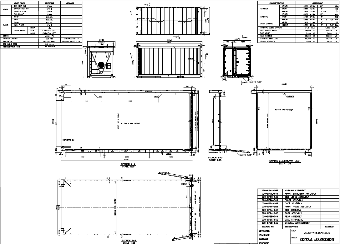
General specification for 20ft door in door customized pallet wide reefer containers for reference.
1.1 OPERATIONAL ENVIRONMENT
1.1.1 Operational Environment
The container is to be designed and manufactured for the carriage of refrigerated (frozen,
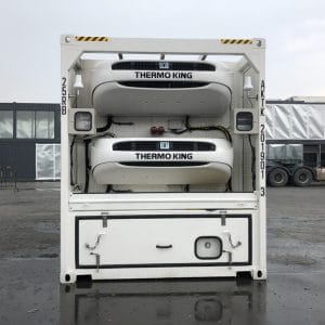
chilled) foodstuffs and general cargo by land (on road or rail) and by sea (above or bellow deck) throughout the world and will range from -30°C to +70°C without effect on the strength of basic structure. A mechanical refrigeration unit of a “one piece picture frame type” will be fitted to the front end frame. The container is designed with a refrigeration unit to maintain the inside space temperature at -25C° to +25C°.
1.2 REGULATIONS AND STANDARDS
1.2.1 ISO/TC-104
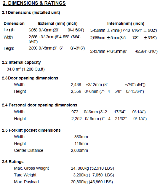
668 Dimensions and ratings (1993 edition)
6346 Coding, identification and marking (the third edition 1995)
1496/2 Specification and testing thermal containers (1996 edition)
1161 Specification of corner fittings (1984AMD.1:2007 edition)
1.2.2 TIR Requirements and Certificate: approved By Classification Society.
1.2.3 Timber Component Treatment and Certificate
There will be no exposed timber in the construction.
1.2.4 CSC Requirements and Certificate
In compliance with “international convention for safe containers”.
1.2.5 Classification Society
All Containers will be certified by ABS / BV / LR.
1.3 HANDLING
The containers will be constructed to be capable of being handled without permanent deformation which will render them unsuitable for use under the following conditions:
1.3.1 Lifting full or empty at top corner fittings by means of spreaders fitted with hooks,
shackles or twistlocks.
1.3.2 Lifting full or empty at bottom corner fittings using slings with terminal fittings at sling angles of 45 deg. To the horizontal plane.
1.4 TRANSPORTATION
The container will be constructed to be suitable for transportation in normal operating conditions and in the following modes:
1.4.1 Marine——- In the cell guide: 5 high stacked (based on 24,000kg) on the deck: 4 high stacked and secured by vertical and diagonal lashings
1.4.2 Road——–On flat bed or skeleton chassis, secured by twistlocks or equivalent ones at the bottom corner fittings.
1.4.3 Rail———-On the flat cars of special container cars secured by twistlock or equivalent ones at the bottom corner fittings.
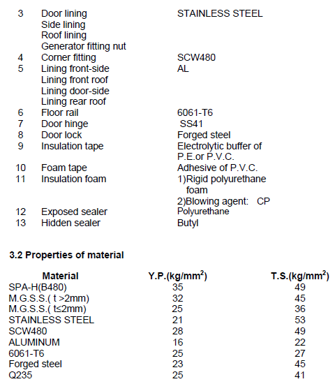
4.1 General construction
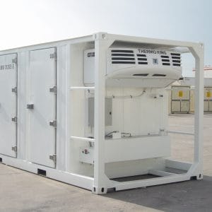
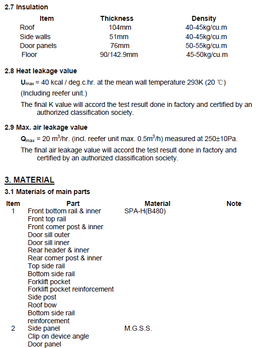
The container will be constructed of steel parts, which are rear and front frame, insulated side with corrugated M.G.S.S. side panel and stainless steel lining, insulated base with aluminum reversed T-shaped floor rail and SPAH(B480) corrugated sub floor, insulated roof with M.G.S.S., corrugated panel and stainless steel lining, insulated door with M.G.S.S. door panel and stainless steel corrugated lining, and Cast steel(JIS SCW480 extended to suit 2.556m wide design). Refrigeration unit will be installed to the front-end frame.
4.2 Base structure & flooring
The floor is composed of corrugated sub floor and “reversed T-shaped floor rail with insulation of polyurethane.
4.2.1 Bottom side rail
SPA-H(B480) / equivalent 4.0mm thick upper rails with 4.0 angle reinforcement and 4.0mm thick lower rails.
4.2.2 Floor rail
Reversed T-shaped extruded aluminum, flat surface is 30 mm high, A 6061-T6.
4.2.3 Forklift pocket
SPA-H(B480) / equivalent 6.0mm thick pressed hat section reinforced by 6.0mm thick bottom plate.
4.2.4 Subfloor
SPA-H(B480) / equivalent 1.6mm corrugated sheets continuously welded to bottom rail and forklift pocket.
4.2.5 Cross member
8 pieces of 4.0 mm thick Square Tube(50*50) beam are set inside of foam and welded to bottom rails.
4.2.6 Drain Pipe
2 auto drains are provided at front and rear end corner (total 4).
4.2.7 Floor stringer
Aluminum angle plates are to be screwed to each PE by full threaded steel screws and Aluminum angle plates are welded to the reversed T-shaped floor-boar
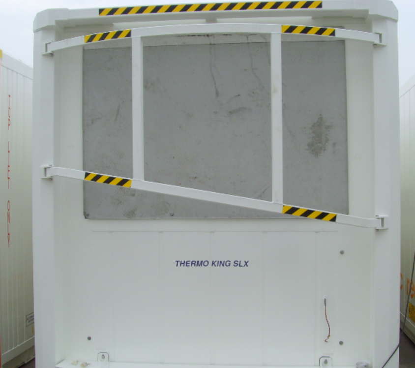
4.3 Front end frame
Front end frame is composed of steel frame members, which is constructed so that refrigerating unit can be fitted.
4.3.1 Front corner post
SPA-H(B480) / equivalent welded construction with 4.0mm thick outer and 4.0mm thick inner reinforcement.
4.3.2 Front sill
SPA-H(B480) / equivalent 4.0mm thick outer plate, 4.0mm thick inner member, and the lower flange of the sill near to corner fitting is provided with hot rolled C section for damage protection.
4.3.3 Front header
SPA-H(B480) / equivalent 4.0mm thick pressed plate with 4.0mm thick protection plate.
4.3.4 Generator Mounting device
It is provided on front header and corner posts for clip on type generator sets. QTY.: 1 set.
4.4 Rear end frame
4.4.1 Rear corner post
SPA-H(B480) / equivalent welded construction with 6.0mm thick outer and 6.0mm thick inner with 14.0mm Q235 flat bar stiffener.
4.4.2 Door header
SPA-H(B480) / equivalent welded construction with 4.0mm thick upper member, 4.0mm thick inner member and 4mm thick protection plate.
4 pieces of 4.0mm thick steel plate will be applied at the behind of each cam keeper location.
4.4.3 Door sill
SPA-H(B480) / equivalent welded construction with 6.0mm thick outer member and 4.0mm thick inner member.
4 pieces of 4.0mm thick steel plate will be applied at the behind of each cam keeper location.
4.4.4 Door Ramp
Ramp has a lip at the right side of the door sill. Checker aluminum plate (Test load (MAX.): 500KG).
4.5 Door
Rear door is composed of M.G.S.S. panel and stainless steel inner lining with polyurethane insulation reinforced by 2 pieces of Ω-beam. One set of door hold-back of nylon rope is provided on each door and a rope hook is fitted on each bottom rail to retain the door from closing. A door keeper is installed which are designed to prevent left hand door from opening before right hand door according to T.I.R. requirements. The personal door is fixed in the right big door, the personal door is composed of M.G.S.S. panel and stainless steel inner lining with polyurethane insulation reinforced by 1 steel frame..
4.5.1 Door panel
door panel: 1.2mm thick muffler grade stainless steel (M.G.S.S.) sheet.
4.5.2 Lining
0.7mm thick
4.5.3 Hinge Lug
6.0mm thick M.G.S.S. plate.
4.5.4 Hinges
10 pieces ,Q235 with grease.
Each door is suspended by 5 hinges with nylon bushes and stainless steel washers placed at the hinge lug of the rear corner post.
4 pieces ,Q235 on the personal door with grease Hinge lug is bolted on the right big door by bolts
4.5.5 Hinge Pin
12.7mm diameter bar, JIS STAINLESS STEEL. Each hinge pin will be riveted to the hinge pin stopper. The personal door hinge pin will be welded with hinge lug for T.I.R
4.5.6 Locking rod assembly
Locking rod assembly: hot dip galvanized.
1 pieces on the right door, 1 piece on the left door. The lock opened from inside will fixed on the personal door
4.57 Installation
Locking rods and hinges installed with stainless steel bolts (AISI 304, T.S. min.70kg/sq.mm).
Bolts to be screwed into nuts that are welded and fastened to the interior panel surface.
4.5.8 Rubber gasket
Outer: E.P.D.M. “C” section double LIP. Inner: E.P.D.M. “O” section. The personal door: E.P.D.M. “e” section.
4.6 Side
4.6.1 Top side rail
SPA-H(B480) / equivalent 4.0mm thick cold rolled profile.
4.6.2 Panel
0.8mm (main) / 1.0mm (outer) thick corrugated M.G.S.S. side panels buttwelded together to form one panel by automatic TIG welding.
4.6.3 Lining
0.7mm thick corrugated stainless steel panels butt-welded together to form one panel by automatic TIG welding.
4.6.4 Side post
SPA-H(B480) / equivalent 1.6mm SPA-H(B480) hat section posts spot welded to the outer panel and welded to the top and bottom rails.
4.7 Roof
4.7.1 Roof panel
0.8mm thick corrugated M.G.S.S. roof panels butt-welded together to form one panel by automatic TIG welding.
4.7.2 Lining
0.7mm thick corrugated stainless steel panels butt-welded together to form one panel by automatic TIG welding.
4.7.3 Roof bow
SPA-H(B480) / equivalent 1.6mm hat section
4.8 Edge covers
All inner edges are covered by stainless steel, PVC sections, all sealed and riveted or glued to the inner lining.
4.9 Corner fitting
Cast steel, JIS SCW480 extended to suit 2.556m wide design
4.10 Unit mounting
The unit mounting is designed in accordance with the reefer machinery manufacturer’s mounting requirement.
The containers will be constructed to be capable of being handled without permanent deformation, which will render them unsuitable for use under the following conditions: When the density of polyurethane foam is 40kg/m³, its thermal conductivity is the lowest. In the actual production process, to ensure that the polyurethane foam has a particular strength, reduces the void rate, and takes into account factors such as leakage during foaming, the design density is slightly greater than 40kg/m³. The wall thickness of the reefer container is generally between 50-120mm, and the partial wall thickness of reefer container for special purposes can be reduced to 30mm.
After the reefer container is loaded, the original quality of the reefer or frozen goods should be checked and stated on the manifest. In the process of packing, the principle of loading and stacking should be strictly complied with to avoid unbalanced cooling caused by short-circuiting cold air and reduce the refrigeration efficiency of the reefer container refrigeration device. When the frozen goods are transported over a long distance, the difference between the set temperature in the box and the set temperature cannot exceed 3°C. For the transportation of reefer goods, the temperature error should not be greater than 0.5°C, preferably not greater than 0.25°C. They transport fresh fruits, vegetables, etc., and the air vents should be opened in time for ventilation.